Saturday, 16 February 2013

Simple, but it works

I have now removed the INA219 breakout board from my Arduino. It took quite a bit of work with the soldering iron to get it off. It is definitely toast. Putting 5v across it and it gets finger-burningly hot pretty quickly. So, I've ordered another one which should be here in a few days.

In the meantime I still wanted to try and get some more charge at 14.4V into my battery. As you may remember the last attempt to charge the battery stopped shortly into the constant 14.4v 'absorption' phase.

So I went old-skool and built a simple voltage divider using a 24K and 10K resistor on a breadboard. I calibrated in software against my digital voltmeter. I wrote a simple Arduino sketch to read the voltage from the analog input connected to the middle of the voltage divider and adjust a PWM pin connected to my MOSFET board accordingly.

I tuned the algorithm a bit to try and stop the oscillation I was seeing before:

void loop() {
  last_voltage = voltage;
  // read the input on analog pin 0:
  int sensorValue = analogRead(A0);
  // Convert the analog reading (which goes from 0 - 1023) to a voltage (0 - 5V):
  voltage = sensorValue * (5.0 / 1023.0) * ((25+10.0)/10.0) * 0.989;
  // print out the value you read:
  Serial.println(voltage);

  if (voltage > 14.4 && voltage >= last_voltage) {
    output_level -= 1;
    if (output_level < 0) {
      output_level = 0;
    }
  } else {
     output_level += 1;
     if (output_level > 255) {
      output_level = 255;
    } 
  }
  Serial.println(output_level);
  analogWrite(6, output_level);
  
  delay(500);
}
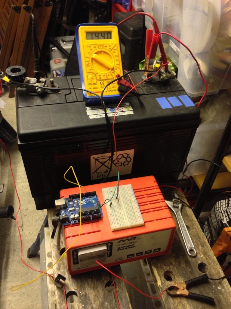
It seems to work and when the charger got to 14.40V it kept pretty close to that value and only oscillated by about 0.01V.

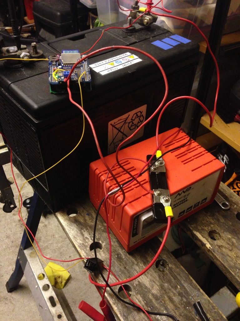
Arduino and breadboard with voltage divider on it to read voltage from battery

I am not able to log the current and voltage like before, so can't produce any graphs, but at least I can give the battery a good absorption charge. I can hear a bit of bubbling going on, so will check in a bit and may adjust the voltage down a bit if it gets too much.

Blown something up :(

Bollocks. Think I've somehow blown something up. After my last blog post I was going back to the garage to put the battery back on charge again. However when I tried to switch it on.... nothing. Taking the logging shield off the Arduino and the Arduino works again. So it is something up with the shield it looks like. My guess is the INA219 has somehow blown. Taking a reading from Vcc to GND on the shield I only get 6 Ohms resistance so seems that something has shorted somewhere. :(

Friday, 15 February 2013

PWM charger works!

I soldered up the MOSFET circuit as per the last post and connected it up to my 'dumb' mains charger to charge one of my batteries overnight. You can just about see the MOSFET in the photo below sat on the bench with the wires coming in and out of it. The wires are red, but it is actually connected to the negative side of the battery.


I initially tried the MOSFET without the heat sink but it got finger-burningly hot. Attaching the heat sink meant you could touch it.

The Arduino was set to start the PWM pin at 0 and whilst the voltage was less than 14.4V increase the PWM output by 10, up to a max of 255 (100% duty cycle, ie. full on). If the voltage is greater than 14.4V reduces the PWM output by 10 to a min of 0 (0% duty cycle, ie full off).

Below is the graph of the current/voltage results:

PWM charging attempt, current and voltage
As you can see the charger only just got to 14.4V by the morning when I switched it off. But you can see it is holding the voltage around 14.4V. I'm not sure if the oscillation around the target voltage is due to my simple algorithm or due to the the fact the charger itself seems to pulse the current (as seen by the green band on the current in the graph). I could probably make my algorithm a bit smarted and get it to check the change in voltage between readings and not just the absolute values. This will probably allow it to converge on the right PWM value better.

My original intention was to hold the battery in absorption stage for a number of hours and watch what happens with the amount of current it accepts. It should get to a point where the change in the rate of current accepted flattens out. At that point I think that battery has taken all it can and the rest is just being converted to heat.

So I'll go out and switch it back on again so it can get some absorption charge. According to this page:


The Absorption time for my 110Ah battery being charged at 2A is 31 hours! That is way higher than I've seen elsewhere, but may explain why my batteries have not been getting enough charge in the past!

Thursday, 14 February 2013

Building a Smarter Battery Charger

I currently have a very 'dumb' mains battery charger. As you may recall, this is the charger that took my battery up to 15.1v last time I tried it. I don't use this charger much, it was bought in an emergency to charge a start battery once upon a time. I've always believed I didn't need a mains charger as my Sterling B2B and solar panel should keep the batteries in my van in a good state. I've since worked out that it looks like they have been undercharging as whilst they have been OK to do a bulk charge, I never went on drives long enough to get to the 'absorption' stage of the charge.

So I've had an idea to build a PWM solar regulator to replace my Stecca PR3030. But I've realised I can use the same circuit to add some 'smarts' to my dumb mains charger. Mainly I need to to make sure that the voltage once it reaches 14.4v is held at that voltage for a few hours as the absorption stage, then drop down to a float charge. So, all I need to do is have something that can restrict the voltage that the mains charger is supplying to the batteries.

My plan is to use a logic level MOSFET to do this, controlled by a PWM pin on the battery monitor Arduino. In short, the Arduino will already be monitoring the battery voltage and so just needs to adjust the PWM rate, lowering it if the voltage goes above 14.4v and increasing it if the voltage falls below 14.4v.

I picked up some 'logic level' MOSFETs from RS today. This particular MOSFET can dissipate 167W and can go up to 40V or 106A. So should be fine to deal with the max 6A at 14.4v = 87W that my mains charger can put out. The idea of a logic-level MOSFET is that the gate pin can be driven directly by TTL voltages from the Arduino (ie. 5V). It is an N-channel MOSFET so will be connected to the negative lead and do 'low side' switching, as opposed to be connected to the positive lead. Connecting to the positive lead means you need more circuitry as the gate pin on the MOSFET has to be pulled higher than the source voltage (ie. higher than 14.4v).

This MOSFET also has a very low resistance between the source and drain pins. A quoted max 0.008 Ohms or 8 Milliohms. This means that at 6A I would get a voltage loss of 0.048V, which is insignificant for the mains charger. It is a bit of a waste for when I use it for solar panels, but seeing as the solar panels have an open voltage quite a bit higher (around 17-20V) then it should be OK. The regulator will be as close to the batteries as possible, so any voltage loss in the wiring from the solar panel to the regulator should happen before we drop the voltage down to 14.4V. This is one of the issues I think I have with my current solar regulator placement. It is halfway between the batteries and the panel and I think doesn't get an accurate reading of the battery voltage.

My plan is to solder the MOSFET to a small piece of stripboard with some screw terminals on the end. I plan to solder the wires along the tops of the copper tracks to provide some more current carrying ability. I also have a small heat sink to attach to the MOSFET to help with heat dissipation. The proposed circuit will be something like this:


The resistor across the pins of the MOSFET is a pull-down resistor, meaning it will keep the gate of the MOSFET closed if the Arduino is disconnected.

Sunday, 10 February 2013

Adjusting fridge temp based on voltage

I stumbled across an interesting message board thread today:

http://www.fieldlines.com/index.php?topic=145714.0

Lots of good pictures and diagrams of someone's experiments with solar and building their own solar regulator.

One thing that particularly caught my attention was later on down the thread they start using a compressor fridge as a dump load for the experiments. They found the built in fridge thermostat drew a large quintessent load when the fridge was not running. They crated their own thermostat which monitored the battery levels and adjusted the temperature depending on what was available in the battery. This meant if they had 'excess' energy coming from the panel then they would chill the fridge to a lower temperature, and if less power available would run the fridge a bit warmer.

I have a compressor fridge in my van and have wondered about doing something along the same lines. My original plan was to have a temp sensor in the fridge and controlled by a microprocessor so that I could set the temperature to a known digital level. Currently you turn a knob inside to set the temperature and I never know exactly what it is set to. So I probably have it set too cold or too warm most of the time which is no doubt in-efficient.

Setting it so that it detect when we are driving and cools the fridge down to a lower temperature when there is excess power coming (from the engine) and maybe runs it slightly warmer at night when there is no power from the solar panel and we are likely to have less power in the battery bank. I could also maybe have different modes depending on what was in the fridge. ie. if I know we have meat int here then then I need to keep it to the correct temperature. If I just have drinks in there then it can afford to run a bit warmer.

The Danfoss compressor in my fridge also has a resistor in the controller in the back that controls how fast the compressor motor runs. I need to check what it is set to, but I think by default it is set to run the compressor as fast as possible. Whilst this means the fridge cools down quicker, it also means that the fridge draws maximum current and probably maximum in-efficiency. It also leads to uneven cooling in the fridge, with some areas frozen with others still warm. If I could control the fridge with a microprocessor then I could adjust the speed of the compressor depending on how the temperature changes. Ie. if the door opens and the temp increases rapidly then run the compressor fast to cool it down and then drop down to low speed to keep it at that temperature.

Saturday, 9 February 2013

Calcium Technology

Doing some more research on what may have happened to my current batteries and how they are performing and I came across some interesting bits. The batteries I have are 'sealed' or termed 'maintenance free'. This is sold by the manufacturers as being a 'good thing'... but as we all know, there is no such thing as a free lunch. The issue here is that the batteries have to be charged much more gently than normal top-uppable batteries.

In order to prevent the excessive gassing that can happen with normal cells which can be topped up, maintenance free batteries have calcium in the plates. This helps prevent the gassing and helps the hydrogen given off to recombine to water inside the cells. The calcium also reduces the self-discharge rate of the battery.

It seems however there is an issue that can arise termed 'Antimony free effect' or 'passivation' which can affect batteries with calcium instead of antimony in the plates such as mine. Fulle details can be read in the comments of this page:

http://batteryuniversity.com/learn/article/charging_the_lead_acid_battery

But in short, a thin layer of lead oxide can form on the plates in the battery. Battery desulphators are not actually removing sulphation, but removing oxidation instead. So I'm hoping that the battery of mine with the desulphator connected might improve.

Doing some more reading, this page describes it in much more detail:

http://www.batteryvitamin.net/sulfation_pulse_treatment_surprise


We believe it to be highly significant that pulsing began gaining popularity in the early 1990s, only after all the major battery manufacturers had introduced low-maintenance and maintenance-free automobile batteries. These batteries have lead-calcium alloy grids. Lead-calcium batteries overwhelmingly fail due to something known in the trade as "passivation" or "open circuit". It has been described by battery technologists as the "antimony-free effect". 
Lead-calcium alloy develops an ultra-thin, very poorly conducting tetragonal lead oxide, (alpha-PbO), layer on the surfaces of the positive plate grids over time, leaving the positive active material in the positive plates isolated from the supporting positive grid structure. Battery manufacturers use tin to control this oxide layer. This is far from straightforward. Addition of more than 1.5% tin to the alloy reduces the passivation effect - critically, at 0.6%, tin actually provides a worsening of the effect. Tin is expensive, so as little as possible is used, with unpredictable results. There are more than 90 patents describing tin, as well as other metals, alloyed with, or plated onto positive grids - suggesting this too, is a highly problematic technology. Silver is even more beneficial but is excruciatingly expensive. Before lead-calcium, lead-antimony was the preferred alloy. Lead-antimony has always been absolutely 100% trouble-free in this regard.


There is also a long article on different charging regimes for sealed lead acid batteries:

http://www.intechopen.com/books/trends-in-telecommunications-technologies/traditional-float-charges-are-they-suited-to-stationary-antimony-free-lead-acid-batteries-

They suggest that the typical approach of holding a calcium/lead battery on float might cause excessive corrosion of the plates and cause premature failure ie. 3-4 year life rather than 20 year design life. They suggest that the battery voltage is allowed to fall and then is periodically given a small current charge at regular intervals to bring the voltage up.

There is also a report done by the US Navy on Calcium batteries used in submarines, which is also an interesting read:

http://torpedo.nrl.navy.mil/tu/ps/pdf/pdf_loader?dsn=5476298

They manufactured some identical cells half with lead-antimony and half with lead-calcium and put them through some charge cycles to see what happened. The lead-calcium ones ended up with very soft paste on the plates that very easily smeared off.

So it does seem that the addition of calcium to batteries versus antimony really is for convenience, but at a trade off of battery life.

Desulphator

It seems battery desulphators are a pretty contentious topic, and some swear by them, some say they are snake oil. I purchased a kit on from Courties Town Marine. I thought it was worth a punt to see if I could revive my dead batteries.

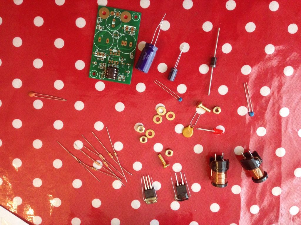
Kit of parts
I did manage to make a mistake on the very first component I soldered in. It was a large diode that I soldered in back to front. I realised as soon as i did it, and then spent about half an hour trying to unsolder it.

I seems that everything it working and that I haven't managed to damage the components with the excess heat.


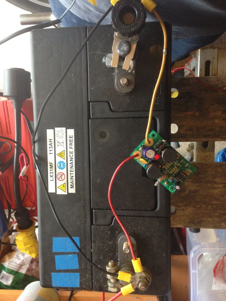
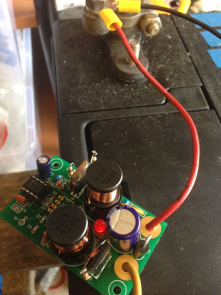
I wired it up to the battery in the garage. This is the one that managed to charge up to 15.1v. It has been sat now for about 4 days and is still reporting 12.90v... which still seems quite high. I connected the desulphator up and the LED has come on and I can here the 1Hz buzz of it as it pulses the battery.


The MOSFET on it gets pretty warm. As in I can just about touch it briefly, but it doesn't melt skin warm. I think this is normal. My multimeter is unable to read the voltage whilst the dusulphator is connected. I'm guessing the, in effect, AC voltage is too much for it.

I'll keep an eye on it to make sure it is not overheating, but you need to run them for several weeks for them to work apparently.

-Matt